
Infra-Red Remote Control Home Appliances
Introduction
Today’s engineering is based on reducing human efforts in affordable prices and this is mostly done by using “Wireless technology and Artificial Intelligence”. The manual switching of any home appliance is an inconvenient method for physically disabled or elders or even normal young guys when frequent switching operation is required. Thus the conventional method of switching operation has to be overcome by using a method of switching. This can be done by an advance switching method like a remote control for electronic home appliances.
Principle
It is strictly based on the working of the infra-red rays. Infra-red radiations extends from the nominal red edge of the visible spectrum at 700nm to 1mm. This range of wavelengths corresponds to a frequency of approximately 430 THz to 300GHz.The Infra-red rays work just like a switch i.e. when the transmitted Infra-red rays will reach the receiver circuit , the circuit will get closed and the device will be turned on.
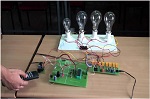
Circuit
It consists of two parts
- Transmitter circuit
- Receiver circuit

The transmitter circuit uses one IC i.e. NE555 which is a pulse generator the NE555 is used in its monostable state i.e. it will be generating a pulse and the time period of the pulse will be calculated by time constant of RC coupling. The 1st pin is ground hence connected to negative terminal of the battery. Second is trigger i.e. it will trigger the circuit when sufficient voltage is applied. The third pin is for output, forth for reset, 5th for control, 6th is for threshold voltage, 7th is discharge and 8th is VCC. In the circuit the NE555 will generate pulse when sufficient voltage is reaching at the 2nd pin of the IC and the pulse generated from the IC will complete the circuit as a result the IR transmitter will emit the Infra-red radiation.
Receiver circuit

The circuit uses phototransistor TSOP 1738 and NE555 timer IC in its bistable state. The signal pin is connected to 2nd pin of NE555 which is the trigger pin of the IC as told earlier. As the phototransistor will receive the Infra-red radiation and this signal will be passed on to the trigger pin of the IC which will further switch on the circuit and the light will be switched on. As the NE555 is in bistable state it will be turned on when a pulse is generated then if second pulse will be given to the its trigger pin then NE555 will be turned off hence, the circuit will be turned off. Thus this will serve the purpose of remote control.
Future scope
It can be used in places like hospitals or for places where handicapped, old or people who cannot move much resides. Research labs of radioactive substances can also use this. If used with counter IC 4017 we can make it usable for switching operation of large number of electrical appliances and can be used in big halls. It is very useful in robotics branch of science.

 Platform © Web-Development